Saturday, 30 March 2013

Mid Semester break - SketchUp Model

First week:

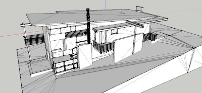
As we have realised that the imported model in sketch up was far too fragmented for us to use.

The original SketchUp model. 

I built the model in SketchUp from scratch by following the original Revit model and the detail drawing from Independent task in week 3.


For the first week of the semester break, I focused on creating structure part of building.
My task was to create the timber framing for the brick veneer, including external walls, floors, roofs, internal walls, the external single brick wall for the brick veneer the double brick walls, the fire wall, mullions for the glazing wall, corrugated iron roof.


I began with creating the base of the building following the measurement of the Revit model. Because the size of the each component such as wall thickness and door sizes does not quiet follow Australian standard, I took the measurement off outside of the external wall face to the other other side of it and worked it in words.
The size of the stairs seemed to be fine so am I keeping the size the same.


SketchUp model first stage

I have began with creating the timber framing such as timber wall stud, bottom and top plates, noggin  and floor joists etc. In order to create the timber framing especially for the skillion roof . I did further research for the timber framing, to decide on the most suitable method for our building. 


Image showing the basic structure of the simple building.


The example of the timber frame model for the skillion roof. 


The photo of the real building showing the timber structure. 


I found out that there are several slightly different way to build the timber framing  for the domestic built in Australia.


Early stage of timber frame model.

The timber frame structure - I have timed the timber frame for the upper level to join the wall and the roof. and I created the fascia all way around the rafter to fill the gap between the roof and the brick skin. 

Single brick walls with timber framing with metal roof sheets and mullion for the glazing wall.

 Double brick walls 

Plaster internal boards 

Meeting:

We had a meeting during the mid-turn break and showed the team members that work I have done.
They all agreed that the model has the right approach. Some details are to be amended.

Things needs to be changed are:
Nogging - needs to be placed in the different heights. The wall type at the lower level should be double brick and upper level should be timber.

As suggested by the team, I uploaded the model and the screen shot of the model in Wiki during the meeting. Pleas see Mid Semester Break in our Wiki.


Timber framing which will be amended. 

Metal roof sheets and internal veneer panel etc..

Internal wall framing to be developed further. 


Second week: 

They were many more components to be created in order to proceed our work into the next stage, After a several days of meeting, I started working on modelling in SketchUp further.
Such as:

  • Internal walls
  • Deck
  • Stairs
  • Hand rails 
  • Awnings etc. 

Going back to the Revit model, there is a exposed roof structure above the living and kitchen area with the metal beam across the entire building. I began researching and planing the detail of exposed   beams structure.

Screen shot of the original Revit model. showing the exposed roof structure.

C shape steel beams are used for the structural beams and  the awning in Revit model. 

 
An example image of the exposed roof structure. 

The image that I followed in order to plan the joinery of the internal wall and the exposed roof structure.


I created internal wall and the beams and supporting columns according to the information that I gathered.


I have made the internal wall panels between the kitchen and bed rooms on the second floor comes up to the beams. The ceiling joists in bed rooms and bath room are placed flat, supported by one of the internal walls and the metal beams, each span of those joists are within 3500 mm therefore there is no need for the beams to be installed. They are canteriverd out to outside, becomes the structure of the awning. The size of beams and joists comply with Australian standard as follow.

Also, I have extended the floor joists out to the deck and created the supporting beams and columns.

I used the details of traditional timber stairs as shown below. 167 mm rise, 330 mm going and 18 landings so it is under the compliance of Australian stranded. upper half of the stairs go through a room so, I made a enclosure with the stringer as below.

The section of one of the stairs. 


And I created 2 different types of handrails as shown. 


There are the image of the model I created so far. All of theses are to be confirmed in the class with the other team members after the break.

Axonometric image of the lower floor. 

Upper floor 

The roof plan

External view

Sunday, 24 March 2013

Week 3 Independent Study

This week,

I worked on the research in order to create the structural components that are missing from the original model in Revit.
I began searching through BCA to find out about the basic Australian construction standards and the type of materials that we can use.

In order to create the detailed model that assembles properly in any kind of program we are using,  it would be beneficial to have the information about the sizes and detailing of each component in the drawing. Also to clarify the structure of the building itself.
I considered it as a starting point.

I looked into some detail drawings, I collected some brochures from construction material companies and drawn some of the detail drawings myself to think through the most suitable component types,
as shown below:

The hand drawings.


These are the drawings that I have made from my hand drawings combined with the information from the charts. The charts are from .................................


 Roof rafters


Timber wall framing 


Below is the section  of the Revit model which does not have any information or detail of the joinery. And beside it is the detail that is required. Also I have included the relevant sizes and notations. 
Footing And Double Storey Section for brick veneer wall. 

The details for the different kind of structures to be considered. Below are the information for them. 
Once we define the the sizes of the brick veneer wall with keeping in mind of other constructions such as double brick wall and timber wall. I expect it should keep the process of the creating the variety clear.


 Variety of the floors slabs for double brick wall 


This is the example of timber wall and engaged piers for the timber floor.

Also I have produced the plumbing diagrams as below. 
Plumbing detail

To create the model of the plumbing details, I have done the research of the connections and the pipework to understand the way the plumbing is located in the wall structure so I can explain the plumbing system to the team members. 


Plumbing parts 


Details of the roof and roof plumbing

I have created the necessary detail drawing for the joinery of the roof in Revit, so that the position and the height of the roof are lined up. 


 Roof rafter detail
Gutter detail


Chart for the size of joists


In addition to brainstorm the process of creating the model in each grouped models, I have created a critical path analysis. The idea here is that, each team members can check through the each component needs to be created, inform everyone else which part we are undertaking when we completed we can cross one bubble out and move on. This would avoid the overlapping our task.


These are to be discussed in the class with the team members tomorrow.


Sunday, 17 March 2013

Week 3 progress

Intention and Research

Now, we have made our teams intentions, we have started researching about the missing details by looking through BCA, AS/NS building code and detail drawings the follows the Australian standard. 

Please refer to David's Blog for our intentions. 

Tuesday, 12 March 2013

Week 2 Progress


For this week we were asked to create wiki page and produce the back brief. 


So, I have sat up the wiki page, created the logo and invited all the team members to join the site on wikispace. And found the access to BCA and posted the address with the username and the password on the wiki for my team member to use.


Access to our Wiki (wikispace)
http://arch-1392-2013.wikispaces.com/


Things we could show in the “Situation Engine” presentation:

Environmental conditions
e.g.:
Location – Appoint the suitable site(e.g. Little Bay Cove) and create the realistic environment in Crysis
Weather – Create the climate for the site in Crisis
Time – the time frame of the construction work.

Object and properties
e.g.:
Type of buildings - Residential.
Equipment - installation e.g.: Add details such as lighting fixtures, window frames and furniture according to the use of building.
Materials - different materials e.g.: difference between masonry buildings and timber buildings.
Construction detail - The placement of the nails and number of beams and trusses.


Interactivity of the program
e.g.:
Walk through - Circulation of the building, door and window opening types, external views from inside, privacy of the house
Sizes – size of building followed, sizes of each components BCA
People – Avatars behaviour in Crysis
Consideration of people using our system.


Suggestion:

We could decide on the rough scheme first together and work in a Revit team for the building design, and a Crysis team for the land scape and site planning and within that teams each one of us can have a particular position… for a start. Each week we could all together discuss about the process and the project scheme in detail etc…

A part from deciding what we want to do technically......
We can all be a members of a committee and assign our self into useful positions.

The positions to be considered are:

Technical Director, Representative - who presents our work in the public.

Chair - Who calls meeting if necessary. Act as spokesman. A person keeps in touch of everybody.

Treasure - Who keeps a overview of the finance of the organisation. A person in charge of time managing.

Secretary - Who keeps record of everything.


The logo of our team 

The banner 


The image showing our wiki home page 

Wednesday, 6 March 2013