As we have realised that the imported model in sketch up was far too fragmented for us to use.

The original SketchUp model.
For the first week of the semester break, I focused on creating structure part of building.
My task was to create the timber framing for the brick veneer, including external walls, floors, roofs, internal walls, the external single brick wall for the brick veneer the double brick walls, the fire wall, mullions for the glazing wall, corrugated iron roof.
The size of the stairs seemed to be fine so am I keeping the size the same.

SketchUp model first stage
I have began with creating the timber framing such as timber wall stud, bottom and top plates, noggin and floor joists etc. In order to create the timber framing especially for the skillion roof . I did further research for the timber framing, to decide on the most suitable method for our building.

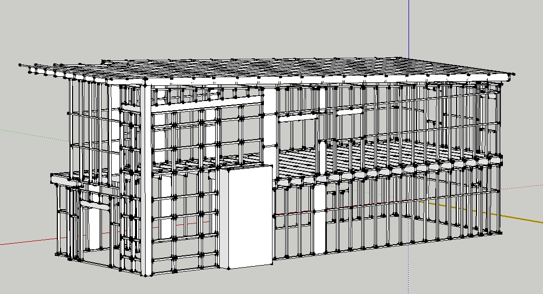
Image showing the basic structure of the simple building.

The example of the timber frame model for the skillion roof.

The photo of the real building showing the timber structure.
I found out that there are several slightly different way to build the timber framing for the domestic built in Australia.

Early stage of timber frame model.
 The timber frame structure - I have timed the timber frame for the upper level to join the wall and the roof. and I created the fascia all way around the rafter to fill the gap between the roof and the brick skin.

Single brick walls with timber framing with metal roof sheets and mullion for the glazing wall.

Double brick walls

Plaster internal boards
Meeting:
We had a meeting during the mid-turn break and showed the team members that work I have done.
They all agreed that the model has the right approach. Some details are to be amended.
Things needs to be changed are:
Nogging - needs to be placed in the different heights. The wall type at the lower level should be double brick and upper level should be timber.
As suggested by the team, I uploaded the model and the screen shot of the model in Wiki during the meeting. Pleas see Mid Semester Break in our Wiki.

Timber framing which will be amended.

Metal roof sheets and internal veneer panel etc..

Internal wall framing to be developed further.
Second week:
They were many more components to be created in order to proceed our work into the next stage, After a several days of meeting, I started working on modelling in SketchUp further.
Such as:
- Internal walls
- Deck
- Stairs
- Hand rails
- Awnings etc.
Going back to the Revit model, there is a exposed roof structure above the living and kitchen area with the metal beam across the entire building. I began researching and planing the detail of exposed beams structure.

Screen shot of the original Revit model. showing the exposed roof structure.

C shape steel beams are used for the structural beams and the awning in Revit model.

An example image of the exposed roof structure.

I created internal wall and the beams and supporting columns according to the information that I gathered.

Also, I have extended the floor joists out to the deck and created the supporting beams and columns.
I used the details of traditional timber stairs as shown below. 167 mm rise, 330 mm going and 18 landings so it is under the compliance of Australian stranded. upper half of the stairs go through a room so, I made a enclosure with the stringer as below.

The section of one of the stairs.

And I created 2 different types of handrails as shown.
There are the image of the model I created so far. All of theses are to be confirmed in the class with the other team members after the break.

Axonometric image of the lower floor.

Upper floor

The roof plan

External view
Great insight into rebuilding a detailed SketchUp model from scratch while refining timber framing, roof structures, and construction details. The careful research and coordination clearly strengthened the project's accuracy. Similar attention to framing precision is essential in professional custom structural framing, where planning and execution directly influence long-term building performance.
ReplyDeleteThis comment has been removed by the author.
ReplyDelete